


SimPRIME is a network simulator targeted to Narrowband Power Line Communications (NB-PLC) networks compliant with the PoweRline Intelligent Metering Evolution (PRIME) standard.
The main objective of this tool is to simulate the behavior of the communication overlay in Advanced Metering Infrastructure (AMI) applications using PRIME technology over DLMS/COSEM. Simulation results will help utilities in estimating the total amount of time required to communicate with all their meter devices. This latency is a key parameter in order to design new strategies intended to a more efficient energy use. For instance, if communications are too slow in a specific network sector, applications requiring quick interactions with meters may not be viable.
In addition to this analysis purpose, the authors of the tool also believe that this could become useful for researching on polling strategies and other MAC optimizations that may lead to a higher network performance. As it is explained later on, PRIME networks have a tree-wise logical structure. This tree is created dynamically depending on the signal coverage. However, the standard does not provide a specific criterion for its creation, leaving some gap for optimization. Once again, a more efficient network will allow for faster responsive applications.
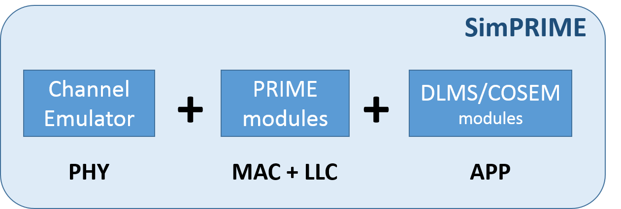
PRIME is a second-generation NB-PLC technology whose development was initially led by the PRIME Alliance, although the specifications of the PHY, MAC, and Convergence layers have been also accepted as standard by the ITU-T recently (ITU-T G.9904).
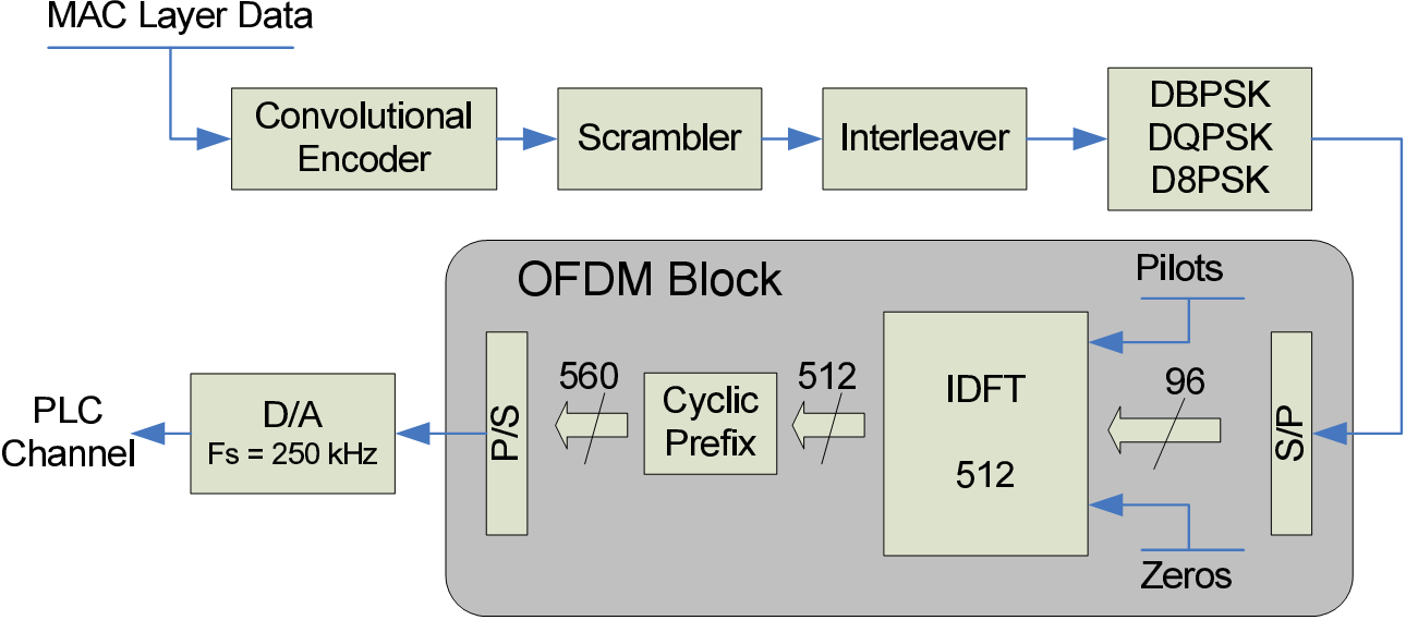
At PHY level, PRIME operates in the CENELEC-A band (specifically in the 41-89 KHz band) and uses Orthogonal Frequency-Division Multiplexing (OFDM) modulation where carriers use Differential Phase Shift Keying (DPSK), allowing raw data rates up to 130 Kbps. However, in practice, manufacturers are currently implementing the most robust option, namely DBPSK with Forwarded Error Correction (FEC) ON, which allows raw data rate up to 21.4 Kbps.
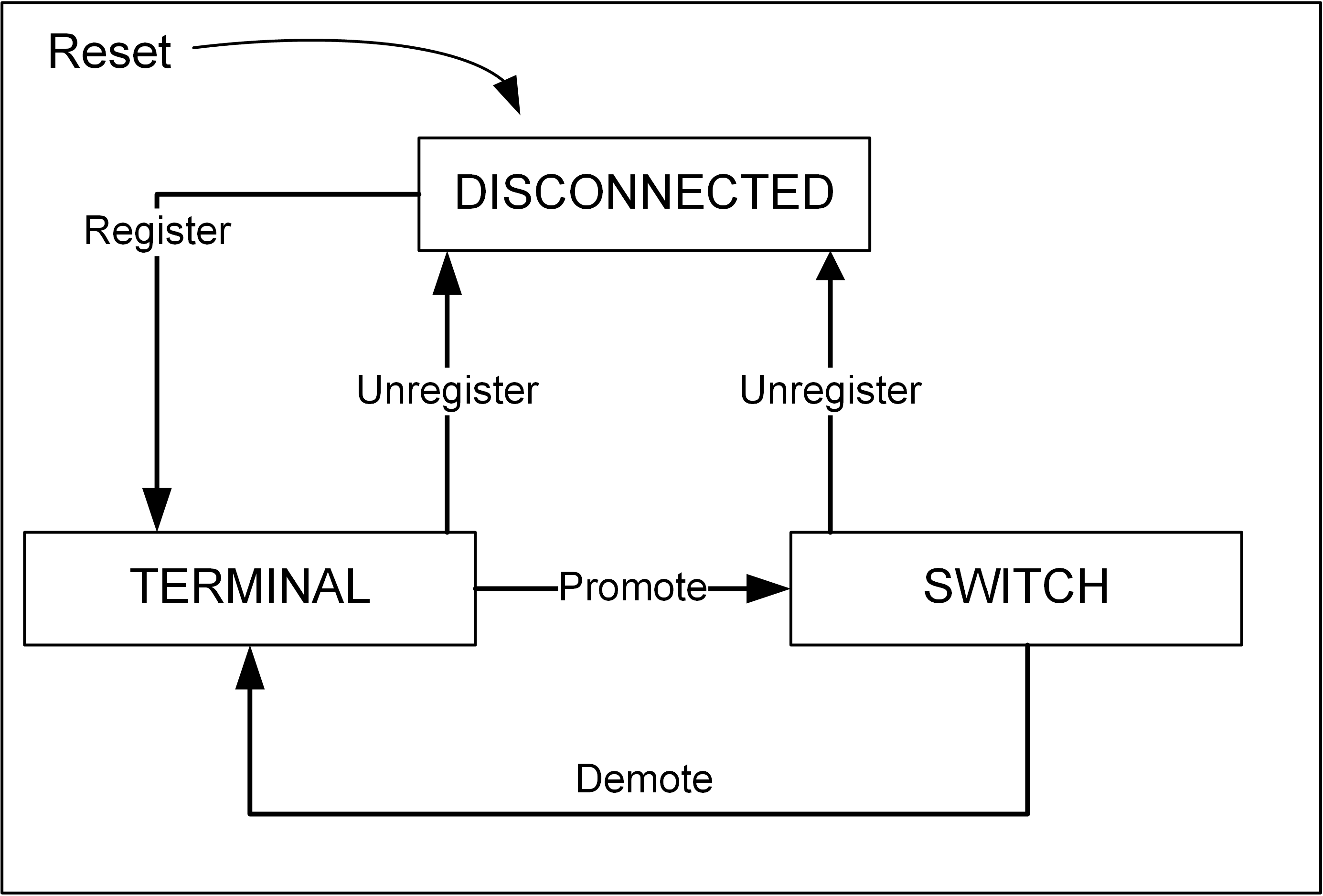
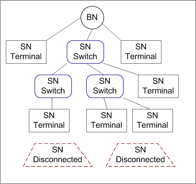
At MAC level, two different kinds of nodes are defined: Base Node (BN) and Service Node(SN). The Base Node has the role of coordinating the PRIME network. Only one single Base Node is allowed in the same PRIME network. In common AMI terminology, the Base Node is known as Concentrator. Service Nodes are generally smart meters.
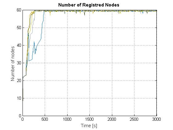
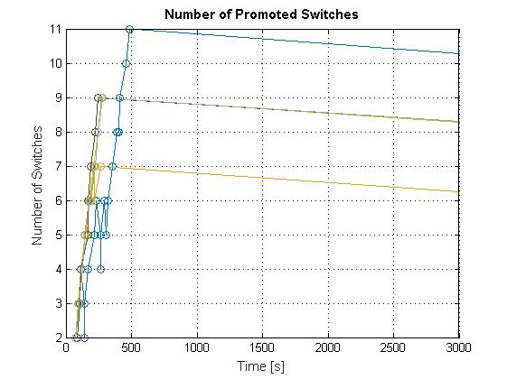
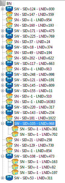
Service Nodes act as leaves or branch points of the logical tree-structured network, as shown in the figure below. The initial state of the SN is Disconnected. They may change to Terminal by registering to the network BN and, only when they are in Terminal state, they can be promoted to Switch.
Switches are communications repeaters whose main goal is to increase signal range in the cable via relying, thus mitigating the effects of attenuation and noise. The position of these switches may influence the behavior of the whole network, as it was argued in [4]. The figure on the right-hand side below illustrates the possible evolution of a SN in PRIME networks.
With respect to the LLC sublayer, it provides mechanisms to perform fragmentation and reassembling of the packets, flow control, automatic repeat request (ARQ) functions and manages the connection phase prior data transmission, since PRIME is a connection-oriented protocol. The LLC sits on top of the MAC sublayer and below the convergence or application layer.
Although PRIME standard only specifies the PHY, MAC and Convergence layers, an application layer is needed in order to have end-to-end communication for AMI. DLMS/COSEM is widely adopted at the application layer in this context. As a matter of fact, it is used not only for electricity meters but also for gas and water meters on top of not only PRIME but also all the other NB-PLC solutions available in the market (e.g., G3, Meters&More, OSGP, CX1). Even with wireless solutions such as Zigbee.
DLMS/COSEM is standardized at the IEC 62056. DLMS is actually the application protocol, whereas COSEM defines the data model.
Download the trial version:simPRIME trial
After installing OMNeT++, the trial can be executed running the following command at the "simulation" folder of the uncompressed file:
../src/iPLC_DLMSCOSEM -r 0 -c DLMSCOSEMSeq1 -n ../src:. iPLC_OpenADR_DLMSCOSEM.ini
In its current state, the simulator allows for the definition of “regular” scenarios. These can mainly be described by the following parameters:
Based on the physical description of the scenario:
Behavior of the end-users:
"Automated" scenarios:
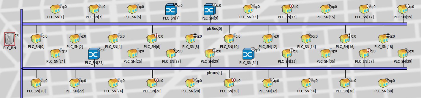
You can see the differente node: Base Nodes and Service Nodes; the former ones can have a Terminal or a Swith role, as described before.
PRIME specification leaves some parameter open to specific implementations. Concrete value ranges are defined, though. SimPRIME allows for the modification of a number of these parameters. This feature becomes highly useful when trying to find out the set of parameter values that outperforms in a given scenario. The following parameters are editable via OMNeT++’s .ini file (See OMNeT++ user manual to know more about .ini files):
In addition to this, the following features are currently under development:
- Instantaneous topology graph, with capability represent evolving changes in dependencies.
- Node geographical location (with or without OpenGIS integration).
This tool has been used to produce part of the data from the following R&D projects and related publications:
[1] Eduardo Alonso, Javier Matanza, Carlos Rodriguez-Morcillo, and Sadot Alexandres. A switch promotion algorithm for improving prime plc network latency. In Power Line Communications and its Applications (ISPLC), 2014 18th IEEE International Symposium on, pages 278-283. IEEE, 2014.
[2] Luís González, Javier Matanza, and Cristina Cordón. Análisis de rendimiento de comunicaciones para lectura de contadores inteligentes. In II Congreso Smart Grids, pages 1-6, 2014.
[3] G López, J I Moreno, H Amarís, and F Salazar. Paving the road toward Smart Grids through large-scale advanced metering infrastructures. Electric Power Systems Research,120:194-205, 2015.
[4] Javier Matanza, Sadot Alexandres, and Carlos Rodriguez-Morcillo. Automatic meter-reading simulation through power line communication. In Modeling, Analysis & Simulation of Computer and Telecommunication Systems (MASCOTS), 2013 IEEE 21st International Symposium on, pages 283-287. IEEE, 2013.
[5] Javier Matanza, Sadot Alexandres, and Carlos Rodríguez-Morcillo. Advanced metering infrastructure performance using european low-voltage power line communication networks. Communications, IET,8(7):1041-1047, 2014.
[6] Javier Matanza Domingo. Improvements in the PLC Systems for Smart Grids Environments.PhD thesis, Pontifical University of Comillas, 2013.
[7] Miguel Seijo, Javier Matanza, Gregorio López, José Ignacio Moreno, and Fernando Martín. Herramientas para evaluación y planificación de redes de comunicaciones para smart grids In II Congreso Smart Grids, 2014.
[8] Miguel Seijo, Jose Ignacio Moreno, Fernando Martín, Javier Matanza, Sadot Alexandres, and Carlos Rodríguez. Poster abstract : "Let There be Light : Unveiling how PRIME Networks Actually Work " Categories and Subject Descriptors. In of the 6th ACM International Conference on Future Energy Systems e-Energy, 2015.


